00 — Why an FSM?
What must this circuit remember?
Combinational logic produces an output from the inputs that exist now. A digital system also needs to respond to a sequence: what happened on earlier clock cycles can change what it should do next. That is sequential logic.
The state register holds that memory. At a clock edge, it loads the next state calculated from the current state and inputs. Reset places it in a known starting state.
State memory
Flip-flops retain the current state between clock edges.
Next-state logic
Combinational logic computes the state to load at the next edge.
Output logic
Combinational logic produces the visible output from state, or state and input.
Moore
y = f(state). Output changes when state changes, normally after a clock edge or reset.
Mealy
y = f(state, input). Output can respond to an input change between clock edges.
01 — Example 1 · divideby3FSM
Three states make a repeating pulse
Start with the smallest possible transition problem: there is no data input. Every rising edge advances one place around a three-state cycle. Reset selects S0.
| Current state | Next state | Output y |
|---|---|---|
| S0 | S1 | 1 |
| S1 | S2 | 0 |
| S2 | S0 | 0 |
Read each row as an edge-to-edge rule. In S1, for instance, y is low now and the next rising edge loads S2.
0430-divideby3FSM.vhdDownload teaching copy ↓type statetype is (S0, S1, S2);
signal state, nextstate: statetype;statetype defines three symbolic values. state is the value held in the register; nextstate is the value waiting to be loaded.
process(clk, reset) begin
  if reset = '1' then state <= S0;
  elsif rising_edge(clk) then
    state <= nextstate;
  end if;
end process;nextstate <= S1 when state = S0 else
S2 when state = S1 else
S0;
y <= '1' when state = S0 else '0';The code follows the same three objects as the diagram and table: the register stores the state, the transition expression selects the next one, and the output expression marks S0 with a high pulse.
Read the timing at rising edges
Starting from reset in S0, each rising edge loads the next state. The output is high only while S0 is held:
y=1
y=0
y=0
y=1
y=0
y=0
y=1
Keep the three views together: the state diagram shows the loop, the table lists each transition, and the VHDL implements exactly those rows.
02 — Reusable implementation structure
Find the three pieces in every FSM
The next two designs add an input, but keep the same architecture. When reading FSM VHDL, identify these parts before following individual conditions.
1 · State memory
A clocked process loads nextstate into state; reset initializes it.
2 · Next-state logic
nextstate = f(state, inputs). Every state and input case must lead to a defined next state.
3 · Output logic
Moore: y = f(state). Mealy: y = f(state, inputs).
03 — Example 2 · patternMoore
Detect 01 by remembering a useful prefix
Now a serial input a supplies one bit per clock. We want a pulse when the most recently sampled two bits are 01. Before looking at VHDL, ask: What does the circuit need to remember about the previous input bits? After a 0, it needs to remember that a 1 next would complete the pattern.
Start at S0, with no useful trailing zero. A sampled 0 moves to S1. In S1, another 0 keeps the same useful memory, while a sampled 1 completes 01 and moves to S2. The remaining arrows prepare for the next match.
| State | What it remembers | a=0 → | a=1 → | y |
|---|---|---|---|---|
| S0 | No useful trailing 0 | S1 | S0 | 0 |
| S1 | Last sampled bit was 0 | S1 | S2 | 0 |
| S2 | Last two bits were 01 | S1 | S0 | 1 |
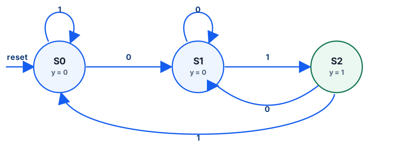
y = 1.In S1, another 0 keeps a useful trailing zero. A 1 takes the machine to S2, where the Moore output is high. From S2, a new 0 starts the next possible match. Thus 0101 produces two detections; no bit must be discarded between them.
0431-patternMoore.vhdDownload teaching copy ↓type statetype is (S0, S1, S2);
signal state, nextstate: statetype;
process(clk, reset) begin
if reset = '1' then state <= S0;
elsif rising_edge(clk) then state <= nextstate;
end process;
process(all) begin
case state is
when S0 =>
if a = '1' then nextstate <= S0;
else nextstate <= S1;
end if;
when S1 =>
if a = '1' then nextstate <= S2;
else nextstate <= S1;
end if;
when S2 =>
if a = '1' then nextstate <= S0;
else nextstate <= S1;
end if;
when others => nextstate <= S0;
end case;
end process;y <= '1' when state = S2 else '0';The output expression mentions state only. If a changes while the state stays S1, y remains low. The detecting 1 must be sampled at a rising edge to enter S2; then y goes high after the state updates.
Trace four sampled bits from reset. Each row shows the state and Moore output after the edge:
| Rising edge | Sampled a | State after edge | y after edge |
|---|---|---|---|
| 1 | 0 | S1 | 0 |
| 2 | 1 | S2 | 1 |
| 3 | 0 | S1 | 0 |
| 4 | 1 | S2 | 1 |
04 — Example 3 · patternMealy
Detect the same 01 with the input on the output path
Can we recognize the same event without creating a dedicated detection state? The Mealy design needs only two states. S0 means there is no useful trailing zero; S1 means the last sampled bit was zero. When the circuit is in S1 and a is currently 1, the pattern is present at the input and y asserts directly.
| Current state | Input a | Next state | Output y |
|---|---|---|---|
| S0 | 0 | S1 | 0 |
| S0 | 1 | S0 | 0 |
| S1 | 0 | S1 | 0 |
| S1 | 1 | S0 | 1 |
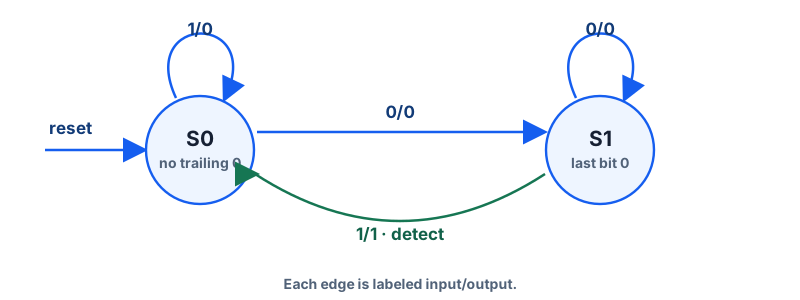
input/output. The green 1/1 arrow detects 01; there is no S2.For a Mealy diagram, label an edge with input/output. The detecting transition is S1 — 1/1 → S0. The output belongs to the transition condition, not to a separate detected state.
0432-patternMealy.vhdDownload teaching copy ↓type statetype is (S0, S1);
signal state, nextstate: statetype;
process(all) begin
case state is
when S0 =>
if a = '1' then nextstate <= S0;
else nextstate <= S1;
end if;
when S1 =>
if a = '1' then nextstate <= S0;
else nextstate <= S1;
end if;
when others => nextstate <= S0;
end case;
end process;y <= '1' when (a = '1' and state = S1) else '0';Its state register is the same clocked pattern as the Moore design: reset sets S0, and each rising edge loads nextstate. The key difference is visible in the output expression: a appears beside state.
For 0, 1, 0, 1, observe the Mealy output just before each sampling edge, while the old state still holds:
| Edge | Input before edge | State before edge | y before edge | State after edge |
|---|---|---|---|---|
| 1 | 0 | S0 | 0 | S1 |
| 2 | 1 | S1 | 1 | S0 |
| 3 | 0 | S0 | 0 | S1 |
| 4 | 1 | S1 | 1 | S0 |
05 — Put the detectors side by side
Same pattern, different output timing
| Property | Moore example | Mealy example |
|---|---|---|
| Output depends on | State | State and present input |
| Output associated with | A state | A transition condition |
| States here | Three: S0, S1, S2 | Two: S0, S1 |
| Response to input | After a state update | Can respond within the current state |
| Timing consideration | Input changes do not directly change y | Input changes can propagate through the combinational output path |
Neither architecture is universally preferable. The Mealy version saves a state and can respond earlier; the Moore version keeps the output independent of direct input changes. Choose according to the interface and timing your system needs.
For a stable input sequence 0, 1, 0, 1, both machines recognize two 01 occurrences. The table below names exactly which side of each edge is being observed.
| Input sampled at edge | Moore state after edge | Moore y after edge | Mealy y before edge |
|---|---|---|---|
| 0 | S1 | 0 | 0 |
| 1 | S2 | 1 | 1 |
| 0 | S1 | 0 | 0 |
| 1 | S2 | 1 | 1 |
The matching values in different columns are not simultaneous output waveforms: the Mealy assertion occurs before the detecting edge; the Moore assertion follows that edge.
Step through the bitstream
Choose the bit present before the next rising edge. Watch the Mealy output in the current state, then clock the bit and see the Moore state and output update.
a| Edge | Input | Moore state after | Moore y after | Mealy y before | Mealy state after |
|---|---|---|---|---|---|
| No bits clocked yet. Try 0, then 1. | |||||
06 — Check your understanding
Predict before you simulate
After reset, the divide-by-3 machine is S0. What are its state and output after two rising edges?
The Moore detector is in S1 and a changes from 0 to 1 before a clock edge. What does y do at once?
Why does the Mealy 01 detector need a state meaning “last sampled bit was 0”?
Discuss a possible answer
If overlaps are allowed, 10101 contains two matches. A Moore design can use four states: no useful prefix, trailing 1, trailing 10, and detected 101. Only the last state's output is high. The key transitions are: trailing 1 + 0 → trailing 10; trailing 10 + 1 → detected 101; detected 101 + 0 → trailing 10. A Mealy design can use the first three states and assert its output on the 1 transition from “trailing 10”; afterward it remembers the final 1 as a possible start of the next match.
07 — Design method
A repeatable way to design an FSM
Work from required behavior toward code. Each step should agree with the diagram and table before simulation.
- Understand the required behavior.
- Identify what the circuit must remember from the past.
- Define states for that information.
- Draw the state diagram.
- Build the transition table.
- Choose Moore or Mealy outputs.
- Write the clocked state register.
- Write the combinational next-state logic.
- Write the output logic.
- Simulate and verify reset, transitions, output timing, and overlaps.
08 — Week summary
State is the useful part of the past
In the three-state machine, state is a position in a repeating clock sequence.
In the pattern detectors, state records a useful suffix of sampled input history.
Find the state register, next-state logic, and output logic in every VHDL FSM.
Moore output follows state; Mealy output can respond to the current input before an edge.
The original source files remain available: divide-by-3, Moore detector, and Mealy detector. Use the linked teaching copies above when compiling with VHDL-2008.