EE 322 · Microprocessors Design
Week 1
Finite State Machines in VHDL
Three designs, one hardware idea: state is the useful part of the past.
Today: read a state diagram, a transition table, a timing trace, and the VHDL that implements them.
00 · The hardware idea
Why does digital design need memory?
Combinational
Output depends on inputs now.
Sequential
Output or next action also depends on what happened before.
Consider detecting two serial bits. The current bit alone cannot tell us whether 01 has arrived.
00 · The hardware idea
State is compressed history
We do not store the entire history. We define states for the distinctions that affect future behavior.
00 · The hardware idea
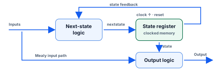
Three blocks, clock, reset
00 · The hardware idea
Separate the questions
Next state
nextstate = f(state, inputs)
Moore output
y = f(state)
Mealy output
y = f(state, input)
The state register loads nextstate at a rising edge. Reset selects a known start.
00 · Design representations
One machine, three views
A diagram shows the paths. A table checks every state and input. VHDL gives those rules to hardware.
Engineering check: these three must agree before simulation.
01 · Divide-by-3 FSM
Start with a cycle, no data input
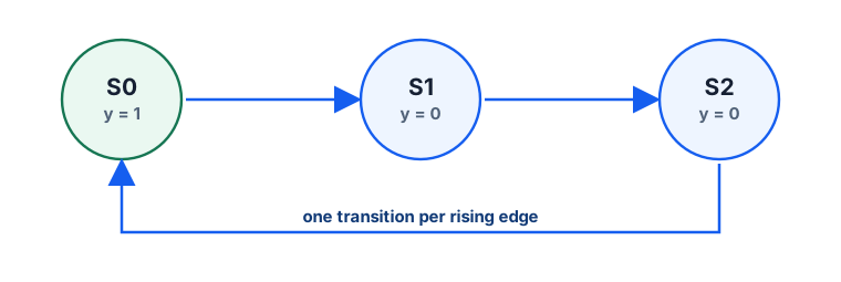
At each rising edge, advance once around three states.
Reset puts the register in S0. Let y be high only in S0.
01 · Divide-by-3 FSM
Every arrow is one rising edge
01 · Divide-by-3 FSM
The same cycle as a table
| Current state | Next state | y now |
|---|---|---|
| S0 | S1 | 1 |
| S1 | S2 | 0 |
| S2 | S0 | 0 |
Point to any diagram arrow; find the same row here.
01 · Divide-by-3 FSM
Name the states
type statetype is (S0, S1, S2);
signal state, nextstate: statetype;
state is the stored value. nextstate is the value computed for the next edge.
From the supplied 0430-divideby3FSM.vhd.
01 · Divide-by-3 FSM
State memory is clocked
process(clk, reset) begin
  if reset = '1' then state <= S0;
  elsif rising_edge(clk) then
    state <= nextstate;
  end if;
end process;
Reset initializes; a rising edge transfers the calculated next state into memory.
Teaching copy: explicit STD_LOGIC comparison; original logic preserved.
01 · Divide-by-3 FSM
Next-state logic follows the arrows
nextstate <= S1 when state = S0 else
             S2 when state = S1 else
             S0;
Read the first line as S0 → S1, the second as S1 → S2, and the final branch as S2 → S0.
01 · Divide-by-3 FSM
Output logic marks S0
y <= '1' when state = S0 else '0';Only S0 makes y high. There is no input on this output path.
01 · Divide-by-3 FSM
One high clock, two low clocks
y=1
y=0
y=0
y=1
y=0
y=0
y=1
The pulse repeats every three clocks. Its duty cycle is one third, not 50%.
02 · Reusable structure
Find these three pieces every time
1 · Register
Clocked state memory, with reset.
2 · Transition
nextstate = f(state, inputs)
3 · Output
Moore: state. Mealy: state plus input.
Keep this architecture while the next two examples add a serial input.
03 · Moore 01 detector
How could a circuit detect 01?
One serial bit a arrives per clock. We want a detection pulse for the sequence 0 then 1.
03 · Moore 01 detector
Give each state a meaning
S0
No useful trailing 0.
S1
The last sampled bit was 0.
S2
The last two sampled bits were 01.
From S1, another 0 keeps S1. A 1 completes the pattern and enters S2.
03 · Moore 01 detector
The detection is a state
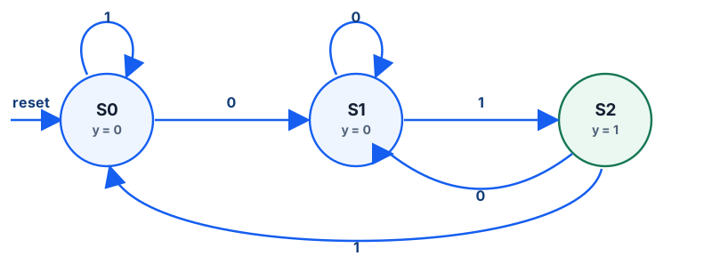
y = 1.03 · Moore 01 detector
Check every input in every state
| State | a = 0 → | a = 1 → | y |
|---|---|---|---|
| S0 | S1 | S0 | 0 |
| S1 | S1 | S2 | 0 |
| S2 | S1 | S0 | 1 |
S2 on 0 returns to S1: that 0 can start another match.
03 · Moore 01 detector
The S1 branch encodes the question
when S1 =>
  if a = '1' then nextstate <= S2;
  else            nextstate <= S1;
  end if;
In S1, a 1 completes 01; a 0 leaves a useful trailing zero.
From the minimal teaching copy of 0431-patternMoore.vhd.
03 · Moore 01 detector
Notice what the output does not read
y <= '1' when state = S2 else '0';Input a is absent. A change on a alone cannot change y.
03 · Moore 01 detector
Trace 0, 1, 0, 1 from reset
| Edge | Sampled a | State after | y after |
|---|---|---|---|
| 1 | 0 | S1 | 0 |
| 2 | 1 | S2 | 1 |
| 3 | 0 | S1 | 0 |
| 4 | 1 | S2 | 1 |
Two overlapping detections: the output rises after edges 2 and 4.
04 · Mealy 01 detector
Can the extra detection state disappear?
S1 already remembers the first half: the last sampled bit was 0.
The output can be attached to the S1 transition instead of a new S2 state.
04 · Mealy 01 detector
Two states; output on the arrow
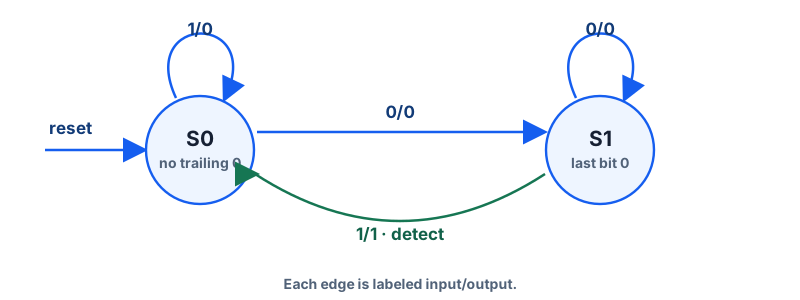
input/output. The green 1/1 edge replaces Moore S2.04 · Mealy 01 detector
Output depends on state and input
| State | a | Next state | y |
|---|---|---|---|
| S0 | 0 | S1 | 0 |
| S0 | 1 | S0 | 0 |
| S1 | 0 | S1 | 0 |
| S1 | 1 | S0 | 1 |
Only S1 with present input 1 detects the pattern.
04 · Mealy 01 detector
The S1 branch has no S2
when S1 =>
  if a = '1' then nextstate <= S0;
  else            nextstate <= S1;
  end if;
After a completing 1, the machine returns to S0. The output expression handles detection.
From the minimal teaching copy of 0432-patternMealy.vhd.
04 · Mealy 01 detector
The present input appears in the output
y <= '1' when (a = '1' and state = S1)
     else '0';
y can rise while S1 is held, before the next edge.
04 · Mealy 01 detector
Observe the output before each edge
| Edge | Input | State before | y before | State after |
|---|---|---|---|---|
| 1 | 0 | S0 | 0 | S1 |
| 2 | 1 | S1 | 1 | S0 |
| 3 | 0 | S0 | 0 | S1 |
| 4 | 1 | S1 | 1 | S0 |
The assertions precede edges 2 and 4; the Moore assertions follow them.
05 · Engineering comparison
Same 01 detector, different timing
| Property | Moore | Mealy |
|---|---|---|
| Output depends on | State | State + input |
| Output attached to | State | Transition |
| States here | 3 | 2 |
| Input response | After state update | Within current state |
| Timing | No direct input path | Input can propagate to output |
Choose based on the output timing and interface you need.
06 · Check the design
Four mistakes to catch early
- Giving a state a name without saying what it remembers.
- Leaving a state/input transition undefined.
- Comparing
STD_LOGICdirectly as if it were Boolean. - Calling the divide-by-3 pulse a 50% duty-cycle clock.
Read the diagram, table, timing trace, and code against one another.
06 · A method to reuse
First design the behavior
- Understand the required behavior.
- Identify what past information matters.
- Define states for that information.
- Draw the state diagram.
- Build the transition table.
06 · A method to reuse
Then implement and verify
- Choose Moore or Mealy outputs.
- Write the clocked state register.
- Write combinational next-state logic.
- Write output logic.
- Simulate reset, transitions, output timing, and overlaps.
07 · Class exercise
Design a 101 detector
For a serial input, decide what the machine must remember after each bit.
- Draw a Moore state diagram.
- Find a Mealy version.
- Should
10101count as one or two matches?
Discuss the meanings of your states before comparing diagrams.
07 · Discuss the exercise
One possible answer, with overlaps
Moore · 4 states
None → trailing 1 → trailing 10 → detected 101.
Mealy · 3 states
Use the first three meanings; assert output on trailing 10 with input 1.
10101 contains two matches. After detecting the first, the final 1 is already a useful prefix for the next.
EE 322 · Week 1
State is the useful part of the past
The three-state cycle records position in time. The detectors record a useful suffix of the bitstream.
In every design: state register → next-state logic → output logic.